Download the PDF Version of this Manual
Click this link to download the manual.
Table of Contents
About the TDR Sensor
Acclima’s TDR Sensors are Integrated Time Domain Reflectometers that contain an ultra-fast step function generator, an ultra-fast waveform digitizer and a precision time base. The step function generator and waveform digitizer are connected directly to a waveguide of length 5 cm, 10 cm or 15 cm without an intervening coaxial cable. The key to their operation is a patented waveform digitizing hardware and firmware set that has an effective digitizing rate of 200 billion samples per second. A step function generator launches a voltage step on the waveguide. A digitizer acquires a digital image of the incident wave and its returning reflections with a resolution of 5 trillionths of a second. The acquired wave image is then analyzed to determine the round-trip propagation time between the incident wave and the first reflected wave. Using the propagation equation that governs the speed of light through a medium the permittivity of the medium is then calculated as:
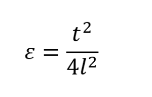
where t is the round trip propagation time, l is the length of the waveguide and 𝜺 is the relative permittivity of the medium though which the wave has passed. The fact that propagation time is independent of soil electrical conductivity leads to the fact that the calculated permittivity is also independent of soil electrical conductivity. This is the main advantage of digitized waveform time domain sensors over all non-time domain electronic sensors. Volumetric Water Content can be derived from permittivity using the Topp equation or a suitable dielectric mixing model. Electrical Conductivity in soils is affected by compaction and hence non-TDR sensors tend to be very sensitive to both installation compaction and follow-on soil settling. TDR sensors report the true volumetric water content independent of soil electrical conductivity, compaction and settling.
An 80 MHz floating point processor inside the sensor is used to process the waveform image. The total time required to send a measurement command to the sensor, acquire the digitized waveform image, process the image, and calculate measurement data is less than one second.
Acclima’s TDR sensors use the industry standard SDI-12 communications protocol and are compatible with any Data Recorder, Reader or Wireless Device that incorporates a compliant SDI-12 Port.
TDR Sensor Models
Acclima offers several models of sensors. These models are available in families that are optimized for different purposes. For example, the TDRxxxH family is optimized for low power operation and can operate at low voltages, while the TDRxxxN family is optimized for high output power and works better in highly saline soils. Each family may have several models that are optimized for different installation methods or environments.
TDR315x Description and Installation
The TDR315x uses a 15 cm waveguide with a rod spacing of 1.9 cm. Because of its larger waveguide it has the largest measuring volume of the three sensors – than being on the order of 100 ml. It can be installed in any orientation but is usually installed by forcing the waveguide rods into the sidewall of a trench that has been dug to the desired depth of installation. This method results in a horizontal installation in undisturbed soil. A special rod guide supplied by Acclima is used to keep the rods parallel while forcing them into the trench sidewall. It can also be installed in the center of a trench and then be backfilled. With this method the backfill needs to be compacted to avoid air pockets near the waveguide and to prevent the creation of a preferential path for surface water to percolate down to the sensor. When the installation is complete the entire soil volume removed to create the trench must be placed back into the trench with sufficient compaction that the backfilled trench surface is even with the surrounding soil surface.
TDR315x Optimum Application
The TDR315x provides excellent readings in all types of soils and has the advantage of a larger sampling volume than the TDR310x and TDR305x. The larger sampling volume makes this sensor an ideal candidate for applications where improved accuracy or reduced susceptibility to foreign objects is desired. Because of the higher impedance waveguide and the longer waveguide length the waveform is more susceptible to attenuation by soil ions than is the case with the TDR310x and TDR305x. Hence the TDR315x is not the best choice for use where the salt content of the soil is exceedingly high.

TDR310x Description and Installation
The TDR310x uses a 10 cm waveguide with a rod spacing of 1.14 cm. The round form factor was designed to match the diameter of a 1” schedule 40 PVC pipe. The top shoulder of the sensor can be glued into the end of a pipe to act as an installation handle. The cable feeds up through the pipe and emerges through a notch at the upper end. The pipe can then be capped off at the upper end to prevent water ingress. The pipe/sensor assembly can them be inserted into a hole that was drilled using a 34 mm flat-bottomed auger. A mallet can be used to pound the top of the pipe and force the sensor waveguide into the undisturbed soil at the bottom of the hole. With the flat-bottomed hole the sideways bias on the waveguide rods is minimal thus allowing the rods to enter the soil in a parallel alignment. This method of installation is generally easier than the trench method used with the TDR315x.
TDR310x Optimum Application
All types of soils are suitable environments for TDR310x measurements. Its sampling volume is only about ¼ of the TDR315x but that is the tradeoff for easier installation. In addition, the TDR310x has a lower impedance waveguide with a shorter length. This makes it more capable than the TDR315x in saline environments.
TDR305x Description, Installation and Optimum Application
The TDR305x was developed from the TDR310x as a measurement solution for soils with exceedingly high salt levels. It provides credible measurements in soils with saturated paste extraction EC levels up to 20000 uS/cm or higher (depending on sensor family). Because of its low sampling volume other form factors would be better choices for applications where salt is not a problem.
Sensor Connection and Setup
Acclima’s TDR sensors use the industry standard SDI-12 communications protocol and are compatible with any Data Recorder, Reader or Wireless Device that incorporates a compliant SDI-12 Port. When sensors are connected to a data recorder, it is recommended to follow the sensor configuration procedures for the data recorder. These procedures should include connecting the sensor and setting an address.
Sensor Connections
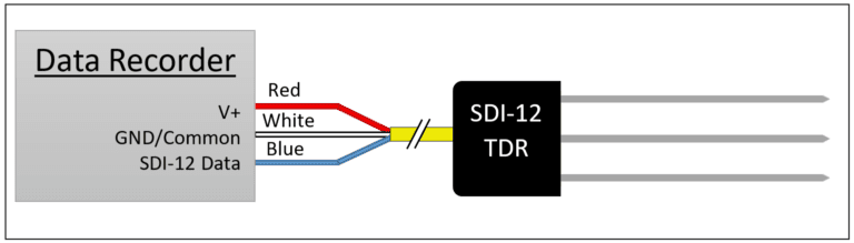
The sensor cable includes 3 wires:
- red = power (Required operating voltage depends on sensor – see datasheet)
- blue = bi-directional data line
- white = return/common/ground for data and power
If a cable is used to connect multiple sensors to the data recorder and if concurrent readings are to be taken the voltage drop in long cables may become an issue. For example: 5 sensors operating simultaneously could draw up to 400 mA of current and cause a voltage drop of 3.25 volts in 250 feet of 22-gauge wire. If the voltage at the sensor drops to the lower operating limit, the sensor may misread or fail to report data. To avoid this do not use concurrent commands or ensure that long cables are of sufficient wire gauge to handle the current loads without significant voltage drops. The SDI-12 command “aV!” can be used to measure the sensor supply voltage at the sensor and help diagnose power issues. However, the “aV!” command is not concurrent, and so it cannot measure the loading effects of concurrent measurements.
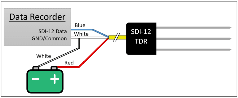
The wiring diagram for the sensor connection to the data recorder is shown below. All sensors are connected in parallel to the terminals on the data recorder or to a cable connected to the data recorder.
Note that if the data recorder and the sensor power supply are separate units, the white wire will need to be connected to the negative power supply terminal and to the data ground or common terminal on the data recorder.
Setting the Sensor Address
The SDI-12 protocol uses an address to distinguish between multiple sensors all connected to the same wire. These must be set uniquely for each sensor wired to a common SDI-12 communications port. Sometimes a single communications port will have multiple connectors to accommodate easily connecting sensors, so care should be taken to understand the configuration of the data reader or recorder.
SDI-12 addresses consist of only a single character. TDR sensors usually ship from the factory programmed with address ‘0’. However, this can be changed to any one of 62 possible addresses including:
- Numbers 0-9
- Uppercase letters A-Z
- Lowercase letters a-z
SDI-12 data recorders and readers should provide a method of assigning addresses to sensors. Consult the manual for these products to find the appropriate procedure.
Setting Addresses using the Acclima SDI-12 Reader
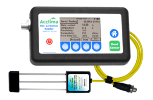
The Acclima SDI-12 Reader provides a very convenient way to check sensor operation and to assign addresses to sensors. With a few button pushes a sensor can be re-addressed. At the same time the reader can be used to take both readings and waveform images from the sensor to assure that the sensor is installed tightly in the soil and reporting properly. GPS coordinates can also be provided from the reader to document the location of the sensor. After each sensor has been individually addressed the full set of sensors can be connected to the data recorder for operation. For more information, visit our website at www.acclima.com.
SDI-12 Command Summary
Acclima SDI-12 sensors implement commands that comply with the SDI-12 specifications. The sensor are compatible with SDI-12 version 1.4 and all earlier versions. For more information about the SDI-12 protocol, please visit the website www.sdi-12.org.
All commands required for full compliance of the version 1.4 specifications are implemented in the TDR sensors. However, the ‘additional measurements’ commands in the SDI-12 specification are meaningless to the Acclima SDI-12 sensors, since permittivity, moisture, conductivity, and temperature are all measured with each available measurement. Hence the response for all the additional/unused measurements commands is “a<CR><LF>” as required by the SDI-12 specification.
If a command is transmitted to the sensor that it does not support, the sensor will ignore it and not respond until a valid command is received.
Command Reference
The table below documents all commands supported by the SDI-12 sensor in alphabetical order. Please note in the table below uses the following substitutions:
a Current sensor address
<CR> Carriage return character (decimal value = 13)
<LF> Linefeed character (decimal value = 10)
Other substitutions may be present and will be described per each command where applicable.
Command | Function | Sensor Response |
?! | Address Query | a<CR><LF> Note: only one device can be connected to the SDI-12 port when this command is used. a<CR><LF> |
a! | Acknowledge Active | a<CR><LF> |
aAb! | Change Address | b<CR><LF> where b in the command and in the response is the new address |
aC!
aCC! | Start Concurrent Measurement Start Concurrent Measurement-Request CRC | a00105<CR><LF>
Reports that measurement takes 1 second and returns 5 values, and then starts the measurement. |
aC1! … aC9! | Start Additional Concurrent Measurement | a00000<CR><LF> No data to be provided in response to this command |
aCC1! … aCC9! | Start Additional Concurrent Measurement – Request CRC | a00000<CR><LF> No data to be provided in response to this command |
aD0! | Send data | Sends the contents of the data buffer, which can be populated by the Start Measurement (aM!), Start Concurrent Measurement (aC!), or Start Verification (aV!) commands. See descriptions below. |
| Previous data-generating command: | Sensor Response to aD0! |
| none/abort
| a<CR><LF>
No data generating command has been issued, or a command was aborted. Data buffer is empty and reports only the address without any data.
|
| aM!
or
aC! | a+VV.V+TT.T+PP.P+BBBB+EEEE<CR><LF> where: + = + or -, depending on the data VV.V = volumetric water content % TT.T = soil temperature degrees C PP.P = soil permittivity BBBB = soil bulk EC in µS/cm EEEE = soil pore water EC in µS/cm |
| aMC!
or
aCC! | a+VV.V+TT.T+PP.P+BBBB+EEEECCC<CR><LF> where: + = + or -, depending on the data VV.V = volumetric water content % TT.T = soil temperature degrees C PP.P = soil permittivity BBBB = soil bulk EC in µS/cm EEEE = soil pore water EC in µS/cm CCC = CRC check. See SDI-12 spec for more info. |
| aM1!…aM9! aMC1!…aMC9! aC1!…aC9! aCC1!…aCC9! | a<CR><LF>
The sensor does not report data for these commands. The data buffer is cleared and no data is returned.
|
| aV! | a+FF+XX.X+YY.Y+TT.T+LLL+EE<CR><LF> where: + = + or -, depending on the data FF = Error Flags (0 = no errors) XX.X = Voltage while sensor is idle YY.Y = Voltage while sensor is active TT.T = Temperature LLL = Waveform Amplitude (0-4095) EE = Error Data |
aD1! … aD9! |
| a<CR><LF> No data for these commands. Some commands may report additional data used for factory purposes. The format or content of this data is not guaranteed. |
aI! | Send Identification | aSSVVVVVVPPPPPPVVVxx…xx<CR><LF> example: 014Acclima TR310W1.320008059<CR><LF> where: a = sensor address (example = 0) SS = SDI-12 protocol version (example = 1.4) VVVVVV= Vendor (example = Acclima_) PPPPPP= Model (example = TR310W aka TDR-310W) VVV= Product Version (Example = 1.3) xx…xx= Serial Number (Example = 20008059) |
aIC!
aICC! | Identify Concurrent Measurement | a00105<CR><LF> Measurement will take 1 second and returns 5 values. However, this does not start the measurement.
|
aIC_001!
aIM_001! | Identify 1st measurement data point | a,MV,%,Soil Moisture;<CR><LF>
Reading Code = MV (Percent Water Volume) Measurement Units = % Short Name = Soil Moisture |
aIC_002!
aIM_002! | Identify 2nd measurement data point | 0,TV,C,Soil Temperature;<CR><LF>
Reading Code = TV (Soil Temperature) Measurement Units = C Short Name = Soil Temperature |
aIC_003!
aIM_003! | Identify 3rd measurement data point | 0,MD, ,Relative Permittivity;<CR><LF>
Reading Code = MD (Dielectric Constant) Measurement Units = [none] Short Name = Relative Permittivity |
aIC_004!
aIM_004! | Identify 4th measurement data point | 0,MN,uS/cm,Bulk Electrical Conductivity;<CR><LF>
Reading Code = MN (Soil Salinity) Measurement Units = uS/cm Short Name = Bulk Electrical Conductivity |
aIC_005!
aIM_005! | Identify 5th measurement data point | 0,WS,uS/cm,Pore Water Electrical Conductivity;<CR><LF>
Reading Code = WS (Water Salinity) Measurement Units = uS/cm Short Name = Pore Water EC |
aIM!
aIMC! | Identify Measurement | a0015<CR><LF> Measurement will take 1 second and returns 5 values. However, this does not start the measurement.
|
aM!
aMC! | Start Measurement
Start Measurement – Request CRC | a0015<CR><LF> Reports that measurement takes 1 second and returns 5 values, and then starts the measurement. a<CR><LF> Sensor returns a Service Request after measurement is made. The data can be retrieved using the aD0! command |
aM! … aM9!
aMC1! … aMC9! | Additional Measurements
Additional Measurements – Request CRC | a0000<CR><LF>
The TDR sensor does not use of these commands. If the command is received the sensor reports “no data” to be returned. |
aV!
| Start Verification | a0016<CR><LF> 6 data items will be returned in 1 second.
a<CR><LF> The sensor returns a service request after the measurement is made. The data can be retrieved using the aD0! Command. |
aXAttt!
| Get Waveform point | aVVV<CR><LF> The sensor responds with the waveform amplitude at time ttt where ttt and VVV are in hexadecimal format, and ttt is in 5-picosecond units and VVV has no units. |
aXI! | Extended Identify | aFwVer=vv.v.v.v,HwVer=x,MfgDate(D/M/Y)=dd/mm/yy where: a = sensor address vv.v.v.v = Full firmware version x = Hardware Version dd/mm/yy = Manufacturing completion date |
Wildcard Address
The TDR sensors support using the wildcard address ‘?’ for any command. Since all sensors will respond to the ‘?’ address, only one sensor should be connected to the SDI-12 port at a time when using the wildcard address. The sensor response will always contain the actual sensor address, independent of wildcard or actual address use in the command.
Testing Communications
To verify that TDR sensor is responding, use the “Send Identification” command “al!” (see table above). The response can be decoded to verify the sensor address, model, version, and serial number as shown in the table above. If the sensor being tested is the only sensor attached to the SDI-12 port, then the wildcard address ‘?’ can be used if the current address is unknown.
Making Measurements with the SDI-12 Sensor
Acclima TDR sensors generate measurement data through two different commands. The data generated by either command is the same, but the commands themselves behave a little differently. These two commands are “Start Measurement” (aM!), and “Start Concurrent Measurement” (aC!).
Standard Measurement Procedure
Due to the relatively high current draw of Acclima TDR sensors, it is usually preferred to use this standard measurement method to prevent voltage drops on the SDI-12 bus. (See Sensor Connections in this document for more information).
The sensor measurement is initiated by issuing the SDI-12 Start Measurement command (aM!). This command does not report measurement data but reports back the amount of time it will take to gather the data, and how many data points will be returned, and then begins measurements. The data recorder then waits for the specified time before returning to collect the data. However, if the sensor is ready to report the data before the time has elapsed, it will issue a service request reply (a<CR><LF>). The data recorder can then immediately fetch the data without waiting the remaining time.
Measure Example, where the sensor address is ‘5’:
Step | Data Recorder | TDR Sensor | Description |
1 | 5M! |
| Data recorder issues Start Measurement command |
2 |
| 50015<CR><LF> | Sensor reports: in 1 second there will be 5 data points available |
3 |
|
| Wait until ready. New commands will abort measurement. |
4 |
| 5<CR><LF> | Sensor sends a service request — the measurement is ready |
5 | 5D0! |
| Data recorder requests the data |
6 |
| 5+23.4+12.3+… | Sensor reports the measurement values |
When gathering sensor data one sensor at a time (which is the recommended method), using this standard measurement procedure will save time and battery power due to the service request – which eliminates the need to wait for the worst-case measurement duration.
When starting a measurement, a CRC check can be requested to be included with the returned data to verify that the data has not been corrupted during transmission. This is done by inserting ‘C’ after the ‘M’ of the Start Measurement command like this: aMC! This will cause a CRC check to be included at the end of the reported data measurement. For more information on CRC checks, see the SDI-12 specification that is available at www.sdi-12.org.
Concurrent Measurement Procedure
When measuring many sensors simultaneously, time and battery life can be conserved by having all the sensors make their measurements simultaneously. The Start Concurrent Measurement command fills this purpose. Care should be taken that the wires and the power supply can handle the load caused by several sensors making measurements at the same time. (See Sensor Connections in this document for more information).
When using the Concurrent Measurement command, the sensor does not return a service request when the data is ready for retrieval. Instead, the recorder is required to wait for the worst-case measurement time requirement before collecting data – as reported by the response to the command. This allows the recorder is allowed to perform other communications to other devices while the sensor is making the measurement and preparing the data.
Measure Example, where the sensor address is ‘G’:
Step | Data Recorder | TDR Sensor | Description |
1 | GC! |
| Data recorder issues Start Concurrent Measurement command |
2 |
| G00105<CR><LF> | Sensor reports: in 1 second there will be 5 data points available |
3 |
|
| The Data recorder waits for at least 1 full second. Communications with other SDI-12 sensors is allowed. |
4 | GD0! |
| Data recorder requests the data |
5 |
| G+23.4+12.3+… | Sensor reports the measurement values |
When starting a concurrent measurement, a CRC check can be requested to be included with the returned data to verify that the data has not been corrupted during transmission. This is done by inserting ‘C’ after the ‘C’ of the Start Concurrent Measurement command like this: aCC! This will cause a CRC check to be included at the end of the reported data measurement. For more information on CRC checks, see the SDI-12 specification that is available at www.sdi-12.org.
Data Retrieval
To retrieve data requested by the “Start Measurement” (aM!), “Start Concurrent Measurement” (aC!), or “Start Verification” (aV!) commands, the data recorder issues a “Send Data” command (aD0!). This command should be issued in proper sequence and can be repeated anytime after the measurement has been completed. See Start Measurement and Start Verification sections of this document for more information on sequencing. If this command is issued before the data buffer has been filled, or after a measurement has been aborted, then it will return no data. The Command Reference in this document describes these conditions.
When a “Start Measurement” or “Start Concurrent Measurement” command has completed, the data buffer in the sensor will contain sensor measurement data. In Acclima TDR sensors, either of these commands will generate the same data. That data will consist of 5 measurements. When the “Send Data” command is issued (aD0!) the sensor will report the data like this:
a+VV.V+TT.T+PP.P+BBBB+EEEE<CR><LF>
an example with actual data returned from the sensor would look like this:
2+24.5+19.5+12.6+534+2345<CR><LF>
These numbers are decoded this way:
Measurement | Coded | Example | Units |
Sensor Address | a | 2 | – |
Volumetric Water Content | +VV.V | +24.5 | % |
Soil Temperature | +TT.T | +19.5 | °C |
Relative Permittivity | +PP.P | +12.6 | – |
Bulk Electrical Conductivity | +BBBB | +534 | uS/cm |
Pore Water Conductivity | +EEEE | +2345 | uS/cm |
Data response complete | <CR><LF> | <CR><LF> | – |
Start Verification
Acclima TDR sensors have an internal check that can detect problems and report them. The SDI-12 command “Start Verification” is used to run a self-check and report the results.
The procedure for running a self-verification test is as follows. This example assumes that the sensor address is ‘4’.
| Step | Data Recorder | TDR Sensor | Description |
| 1 | 4V! | Data recorder issues Start Verification command | |
| 2 | 40016<CR><LF> | Sensor reports: in 1 second there will be 6 data points available | |
| 3 | Wait until ready. New commands will abort measurement. | ||
| 4 | 4<CR><LF> | Sensor sends a service request — the verification is complete | |
| 5 | 4D0! | Data recorder requests the data | |
| 6 | 4+0+11.9+… | Sensor reports the verification results |
The data collected in response to the “Send Data” command (aD0!) has the following format after a “Start Verification” command has completed:
a+FF+XX.X+YY.Y+TT.T+LLLL+EE<CR><LF>
an example with actual data returned from the sensor would look like this:
4+0+11.9+11.5+20.2+3021+0<CR><LF> (No errors reported)
These numbers are decoded this way:
| Data | Coded | Example | Units |
| Sensor Address | a | 4 | – |
| Error Flags | +FF | +0 | – |
| Idle Voltage | +XX.X | +11.9 | V |
| Active Voltage | +YY.Y | +11.5 | V |
| Temperature | +TT.T | +20.2 | °C |
| Waveform Amplitude | +LLLL | +3021 | units |
| Error Data | +EE | +0 | – |
| Data response complete | <CR><LF> | <CR><LF> | – |
Error flags are as follows:
| Error flag | bit | Value | Corrective action |
| Measurement Math Error | 6 | 64 | If there are no other errors, report the Error Data value to Acclima for help. |
| High Conductivity Error | 5 | 32 | Remove metal that is touching the sensor rods or remove the sensor from the very high conductivity medium. |
| Temperature out of range | 4 | 16 | The sensor is beyond operating temperature range, or the temperature sensor has been damaged. |
| Active Voltage error | 3 | 8 | The input voltage is not within operating parameters when the sensor is active. Are you providing adequate power? Do you have high resistance losses in the battery or cable? |
| Idle Voltage error | 2 | 4 | The input voltage is not within operating parameters when the sensor is idle. Check power source. |
| Incident wave does not rise | 1 | 2 | Waveform error. Check for conductivity problems. |
| Incident wave starts high | 0 | 1 | Waveform error, possible dead sensor. |
To decode the errors, subtract the highest error flag value possible from the reported error flags. Continue this procedure until the error flag value is zero. Each subtracted flag value is a reported error. Example:
| Reported Error Flags | Subtracted Error Flag | Meaning |
| 96 | Error flags reported by the sensor | |
| -64 | Measurement error. Other errors exist that can be resolved, so no need to call Acclima yet. | |
| 32 | New error flags value – errors still exist | |
| -32 | High conductivity error | |
| 0 | No more errors. |
Retrieving the TDR Sensor Waveform
The Acclima TDR sensors were developed as Time Domain soil permittivity and moisture content measuring devices but have application in many other research disciplines. TDR waveforms contain much more data than soil moisture content. Soil electrical conductivity can be determined from them. Also, other properties of the soil have an influence on the characteristics of the waveform – hence it is appropriate for some researchers to use TDR waveforms in characterizing these additional properties. The spectral content of the Acclima TDR waveforms is well preserved since there is no low pass filter (coaxial cable) between the waveguide and the digitizer. These factors provide an opportunity for additional time domain and frequency domain analyses of the waveform that can yield additional characteristics of the medium. Special commands are provided for downloading waveforms to be used for these purposes.
The most convenient approach for capturing a waveform is to use the Acclima SDI-12 Reader. A simple button push will cause the sensor to gather the waveform, compress it to save time in communicating it and then send it over the SDI12 cable at an elevated baud rate. The entire process takes about 6 seconds – most of which is communications time. The waveform can then be retrieved from the reader memory using its USB port. The waveform points are stored in .csv format.
Retrieving a waveform without the Acclima SDI12 Reader can be done using the extended SDI-12 command:
aXAtttt!
Where ‘a’ is the device address, ‘XA’ is the extended command code to report a point on the waveform, ‘ttt’ is a hexadecimal time ordinate in 5ps units and ‘!’ is the command terminator. This command returns a hexadecimal string which represents the waveform amplitude time ordinate specified.
Example: Request amplitude of waveform at time 1100 pico-seconds
- Convert the time to 5ps units: 1100 / 5 = 220
- Convert the 5ps time into hexadecimal: 220 => 0DC
- Transmit the request (assumes address = 1): 1XA0DC!
- Get the response string – for example: 18E6<CR><LF>
- Strip off the address (1) and the terminator <CR><LF> = 8E6
- Convert the code from Hexadecimal into decimal: 8E6 => 2278 amplitude units
The entire waveform can be downloaded by requesting successive points in time. This process will take several minutes, and the sensor must be kept perfectly still throughout the process, as each point is measured at the time of the request.
Waveforms can be acquired more quickly using Acclima’s DataSnap products with the SnapView software, or by using the Acclima SDI-12 Sensor Reader. These products dramatically speed up the download time by compressing data in using increased communication data rates that are not SDI-12 compliant. Because of the high data rates, this type of waveform acquisition does not usually work well over long cables (greater than 10-20 meters).
Contact sales@acclima.com with questions.
Acclima, Inc.
1763 West Marcon Lane, Ste. 175
Meridian, ID 83642 USA