Electrical safety
Electrical Specification USB Port Input Voltage: 5VDC, ±0.5V Input Current: 400mA Max Solar or External Supply Input 5 -10 VDC SDI-12 Output Signal Voltage: Typically, 0-5VDC Power Output Voltage: 12VDC Short Circuit Current: 400mA ±20%
Operational safety
Before installation of the system, carefully read all manuals and documentation regarding the contents of the packages sent.
Before use, ensure all products are free and clear of any damage, especially to the mainboards and battery terminals. If any damage or defects are visible contact your dealer immediately. Avoid short circuits by keeping any loose metals, screws, or paper clips away from the inner workings of the products. Avoid allowing internal components to be exposed to dust, water, and extreme temperatures. Operating temperature range is 5° C to 45°C.
Environmental operating temperature
Humidity: 0 to 90% RH, Non-condensing -10 to +50°C (+14 to +122°F)
Note: This limitation comes from the lithium-ion cell.
Introduction
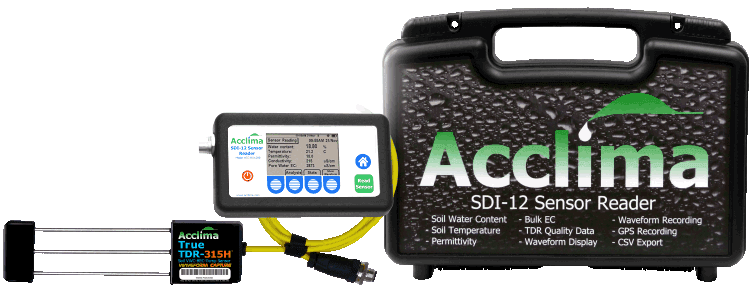
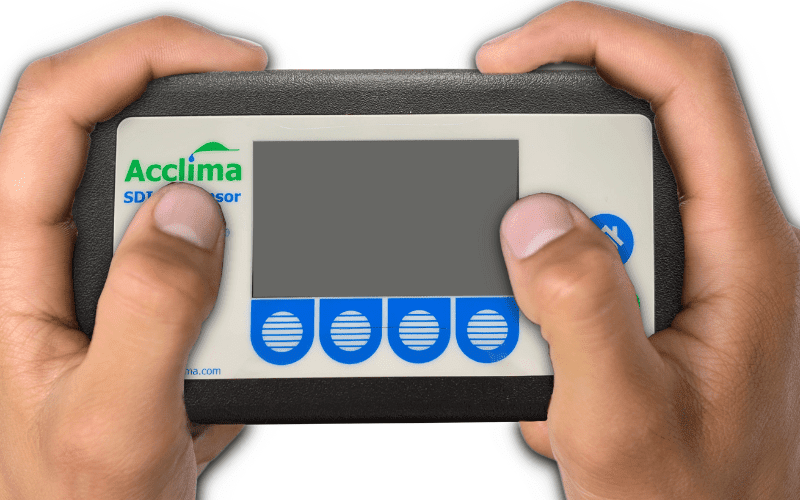
The Acclima RD1200 is a multi-function SDI-12 reader designed to collect readings from SDI-12 devices in a handheld form factor. Optimized for Acclima sensors, it can capture five data point replies to [M!] measurement commands. The Reader can view waveforms and create user-defined sensor thresholds and address sensors without the aid of a Windows PC. The RD-1200 can view statistics and analyze data points on the fly in a user-friendly and easy-to-use form factor.
Specifications
Rugged Enclosure
2.5 LCD Screen (Mono)
3.7v Lithium-ion Battery
M-12 Connector
Micro USB-B port
GPS
Built-in speaker
PSA Before Connecting SDI-12 Devices
The M-12 connector is designed to provide an excellent connection between the reader and the sensor/device. The M-12 connectors are keyed and can only be inserted in one orientation. Once the M-12 plug and connectors are joined, a screw at the top of the plug should be screwed down onto the connector. The screw should only be manipulated by fingers and no tools should ever be used to tighten the two components together. When turning the M-12 locking nut, the screw will stop after only 2 ½ to 3 turns. This is normal and no attempt should be made to screw down the locking nut further after it has become finger tight.
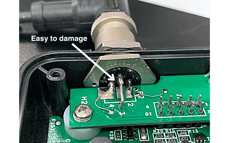
If over-tightening does occur, it will cause damage to the internal components responsible for the connector’s functionality. Efforts have been made to increase the component’s resilience. However, if tools are used to over-tighten and loosen the plug from the M-12 connector, the connector will fail once internal leads have been severed.
Layout
Acclima Reader RD1200 Exterior Layout
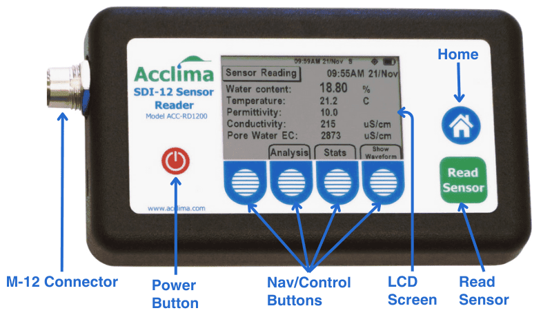
Display Icon Tray Legend
![]()
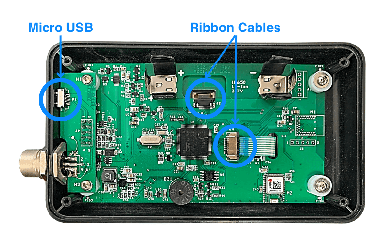
Delicate components
M-12 Connectors
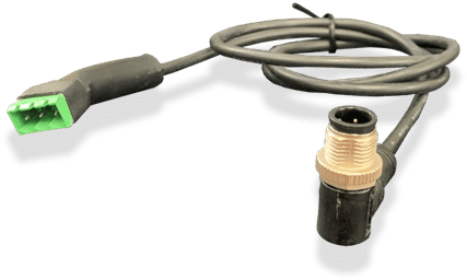
A sensor with an M-12 connector may be easily plugged directly into the Acclima Reader 1200. Plug the keyed male M-12 connector on the end of the sensor’s cable into the M-12 port on the Acclima Sensor Reader. Tighten the lock nut by turning it clockwise until it is finger tight. The locking nut will only turn around the connector twice.
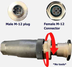
Note: Over-tightening the M-12 screw may cause damage to the leads on the daughterboard. Stop turning the screw once it is finger tight.
Micro USB
The provided Acclima USB interfaces with the Reader via a micro-USB port. This port is directional, and any device being plugged into the port must be in the right orientation for the device to function. Do not apply to much force inserting the USB device into the Reader or face the risk of damaging the micro-USB port or device.
Ribbon Cables
Ribbon cables are in-use internally in the Reader. No attempts should be taken to manipulate the ribbon cables unless done so by an Acclima repair agent. The ribbon cables and their connectors are extremely delicate and cannot be repaired once damaged by the handler.
Display
The 2.5” Monochrome LCD is protected by a hard plastic, coated in a hardened clear epoxy solution. The Reader is not drop-resistant and repeated falls on hard surfaces can cause the LCD to become damaged. We recommend handling the Reader with care.
Accessories
Quick Connect Cable
The Acclima Quick Connect Cable is a versatile accessory that allows easy pairing between a variety of different sensors.
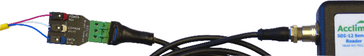
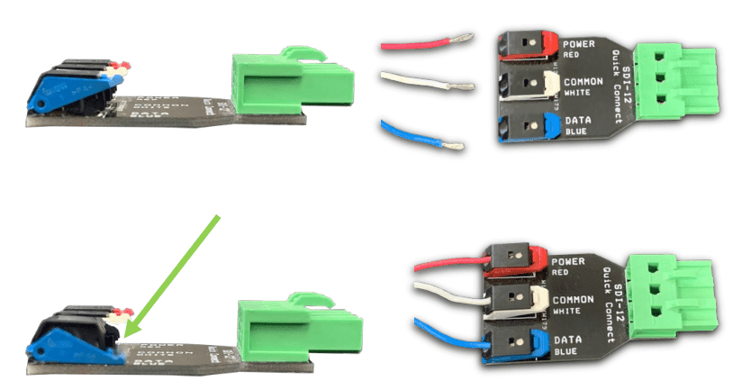
The ‘Quick Connect’ component allows un-terminated SDI-12 wires to be inserted into clamps by pressing down onto the clamp to open its port. Once the wire is inserted the clamp can be released and the port will close onto the wire terminal.
With the sensor attached to the ‘Quick Connect’ it can be plugged into the ‘Cable’ which has a female SDI plug on one end, and a male M-12 connector on the other end. This allows interfacing between the Quick Connect and/or any other SDI-12 devices with a terminal block to be connected to the Reader.
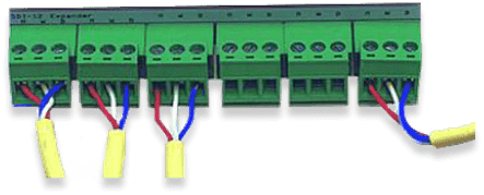
Multi-Port Expander
Using a Multi-port Expander in addition to a Quick Connect Cable, allows for multiple SDI-12 devices to be connected to the Reader at once, via dual wire splices. The Reader can detect up to 62 sensors at once, provided that they are all attached and uniquely addressed.
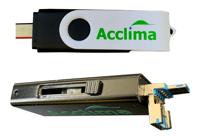
USB 2.0 Flash Drives
Acclima USB 2.0 drives have both a micro-USB covered by a cap on one end and a USB-A connector on the other end. Readers with firmware version 1.7.0 and older, support flash drives with a micro-USB adapter, using the FAT32 (MBR) format.
Readers with firmware version 1.7.1 and newer, support exFAT and FAT32 file formats.
SDI-12 Devices
Sensor Orientation
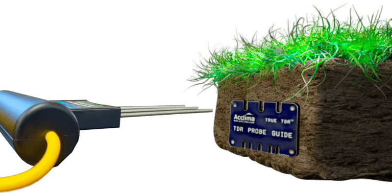
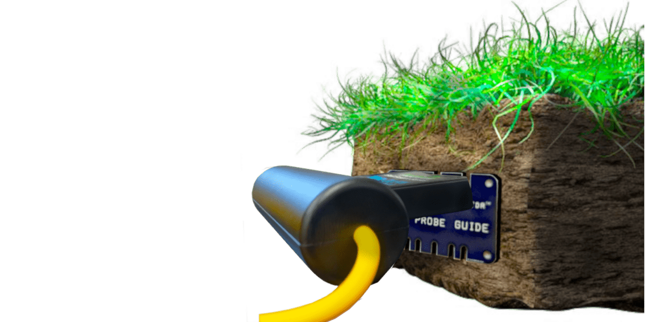
Sensors should be installed in the region of interest where soil moisture measurements are desired. Acclima sensors measure the average volumetric water content over the length of the sensor rods.
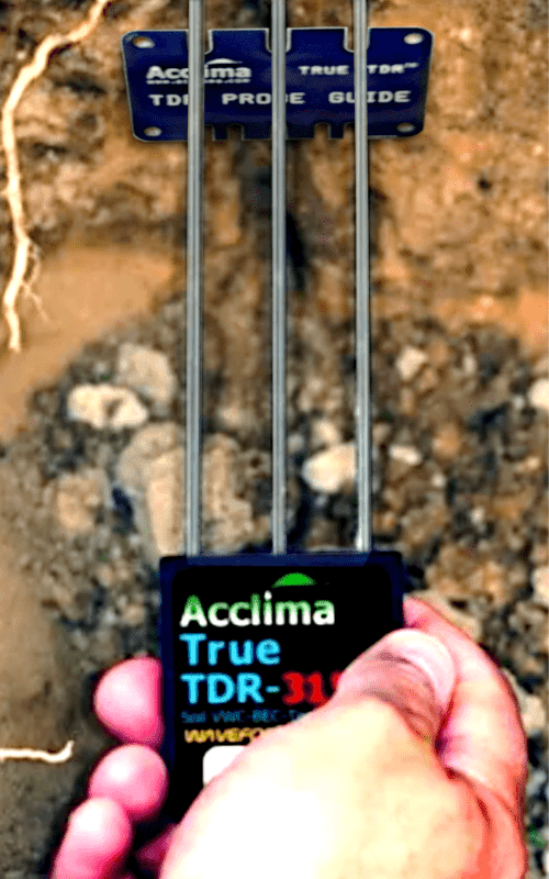
Sensors can be inserted in any orientation and will produce average readings as follows:
- Flat/Horizontal: Provides a moisture reading at a discrete depth. This orientation is frequently used when monitoring plants with shallow roots such as turf, or when multiple sensors are used to create a soil moisture profile vs. depth. • Vertical: Provides average moisture reading over a depth of about six inches. Often used when monitoring deeper root systems such as trees.
- Edge-Horizontal or diagonal: Provides average moisture reading over a variable depth.
We recommend using a waveguide insertion tool to help guide the waveguide/rods into the media wall. This helps to prevent air gaps from forming around the sensor waveguides.
For routine sensor insertions, a Wide-Body Sensor Handle can be added as an upgrade option to make regular sensor insertions easier.
Note: Avoid placing the sensor near rocks or other similar objects. Small roots near the sensor are acceptable and desirable. Avoid large woody roots.
Settings
Start-Up Sequence
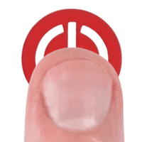
You can turn the Reader on or off at any time by pressing the red power button.
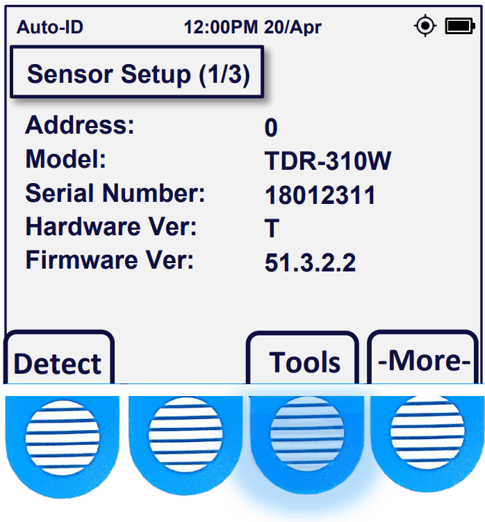
When the Reader is powered on, a boot screen appears containing hardware information. Here, you can see the firmware version, the serial number, and the hardware revision.
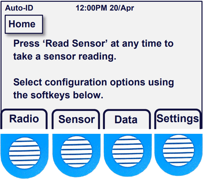
Home
After the boot logo has passed you will be brought to the home screen. The home screen can also be reached at any time by pressing the ‘home’ button found to the right of the display.

From the home screen, the four primary navigation options are made available. Radio, for GPS settings; Sensor, for sensor settings; Data, for data exportation and Settings, for system configuration settings.
Settings
After pressing the ‘Settings’ button, the following configurations may be adjusted by the user.
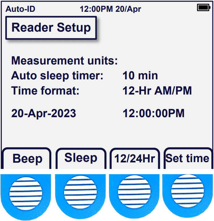
The Beep option allows the user to adjust the speaker volume. This changes the sound level for button presses and sensor readings. The volume can be set to low, high, or off. Press Home>Settings.
The Sleep option adjusts the auto-sleep timer, which is the time that the Reader will be allowed to remain inactive before auto power-off occurs.
The 12/24Hr option changes the clock to run in either standard or military time.
The Set time option allows the user to adjust the clock to correct for Daylight Savings time in their time zone.
Getting Started
General Setup
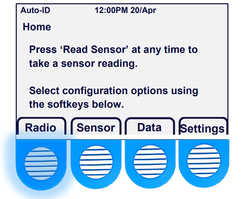
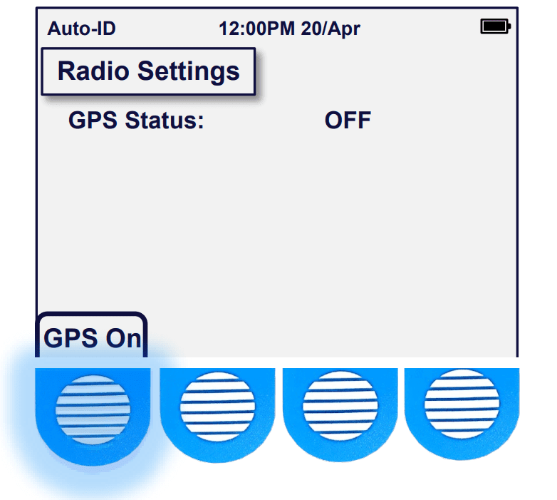
From the ‘Home’ screen you will see a menu of selections above the blue and white-striped membrane buttons. Press (and release) the soft button under Radio.
Another screen will appear with one menu option ‘GPS OFF’. Press the same button to turn the GPS Radio ON.
Subsequently, you will see a stop-watch counter run as the Reader synchronizes with GPS satellites overhead. You must be outside to receive a clear signal.
Try to have a direct line-of-sight to the sky from horizon to horizon when turning on the GPS Radio. If a clear line-of-sight from horizon to horizon isn’t available, try to find an area with a lot of viewable sky. It usually takes 10 – 15 seconds to sync-up and acquire the signal. This may vary depending on your geographic location and other factors such as dense cloud cover and/or tall obstructions such as buildings and trees with dense foliage.
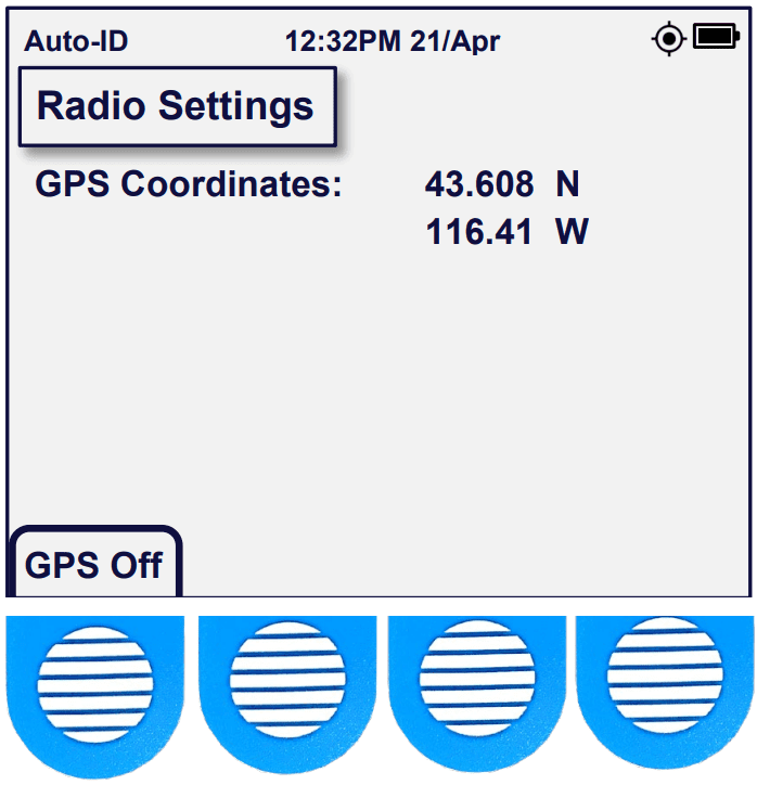
The time on your reader will be updated after synchronization with GPS satellites (but you may need go to the ‘Home’ screen, choose ‘Settings’ and choose ‘Set time‘ to change your time zone) or adjust for Daylight Savings Time.
Press the ‘Home’ button to return to the main menu.
Sensor Data
Reading the Sensor
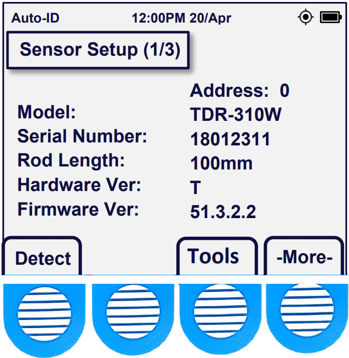
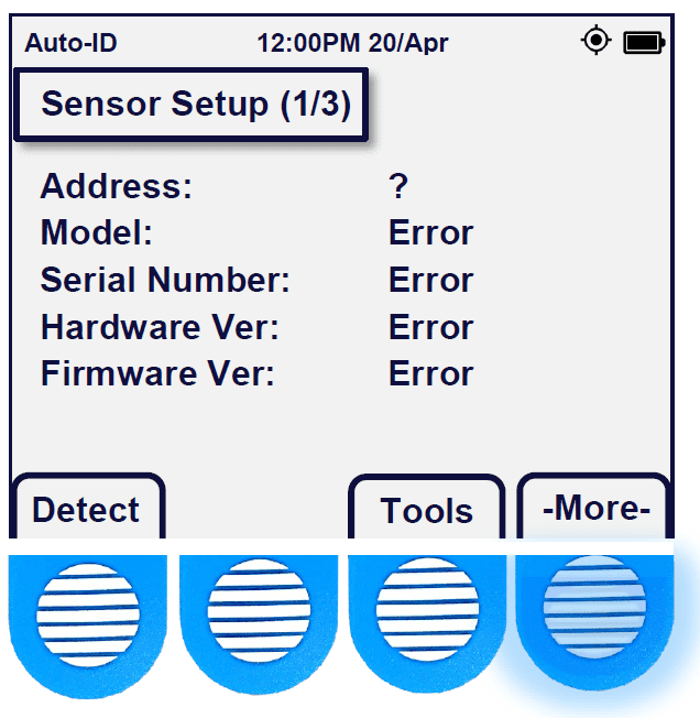
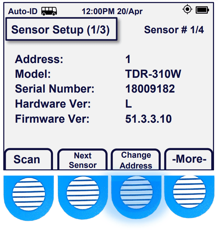
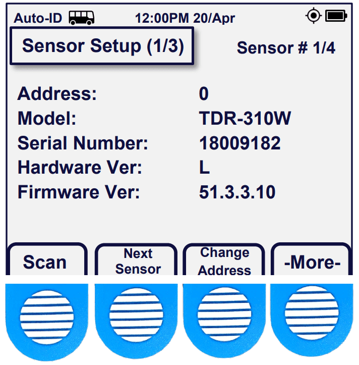
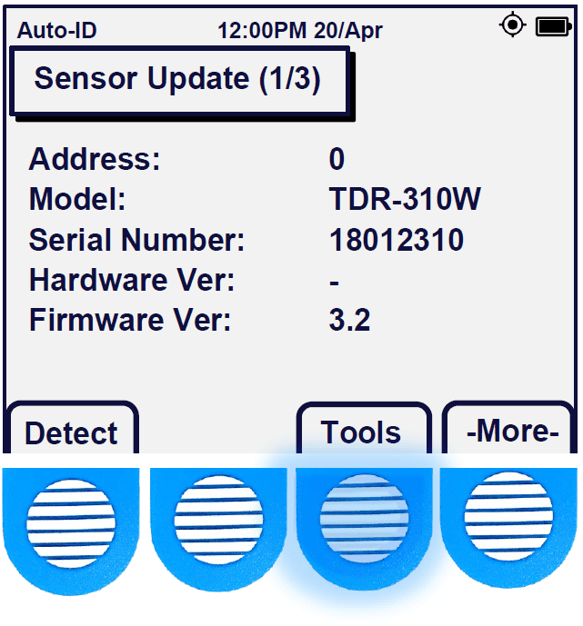
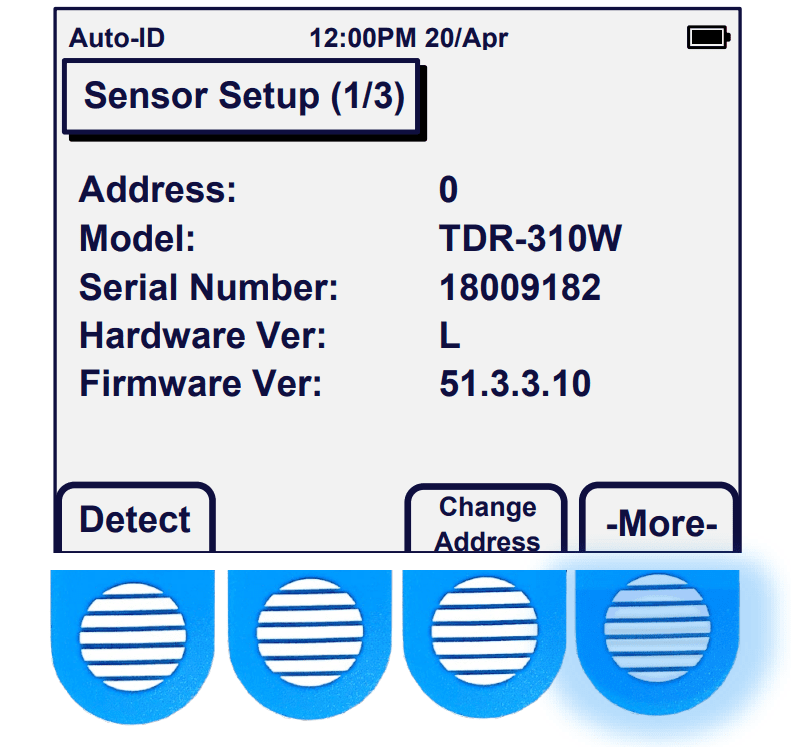
A sensor’s details can be found at any time if you are on the home page and the ‘Sensor’ option is pressed. The sensor’s address, model, serial number, hardware, and firmware become visible on the ‘Sensor Setup page 1/3’.
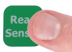
To collect SDI-12 device readings with an Acclima Reader. First, verify a firm connection has been established with the sensor. Check that the locking nut has been screwed down correctly and is finger tight. Make sure that the Reader is powered [On] and press the ‘Read Sensor’ button.
Note: If more than one sensor is connected, you will need to enter the Reader into Bussed Mode.
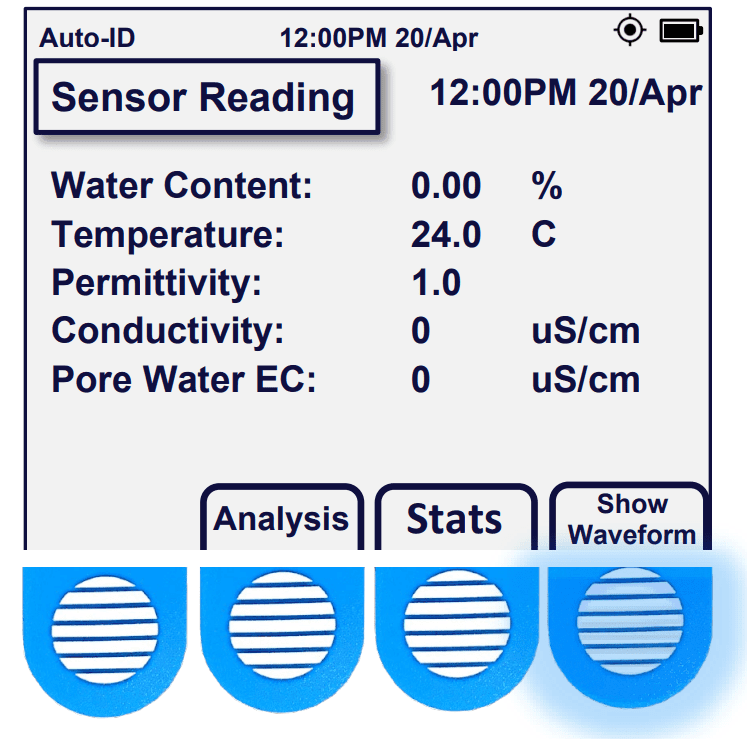
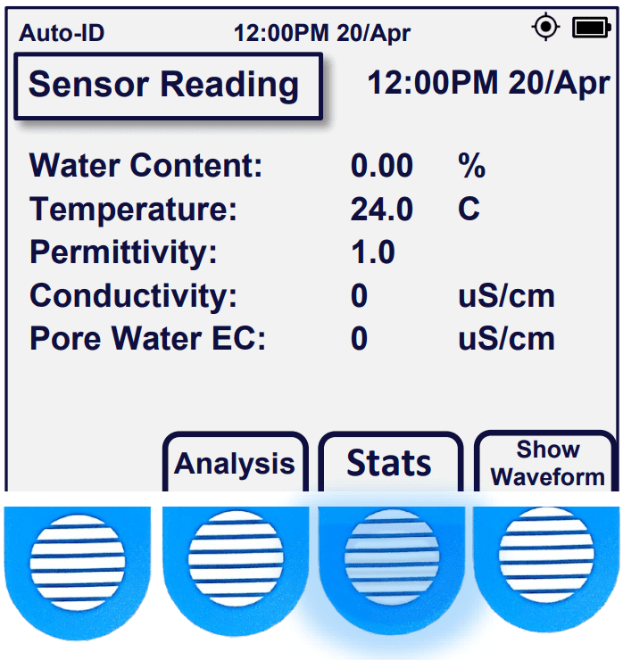
The Sensor Reading will be displayed on the Reader. The ‘Sensor Reading’ screen presents the Volumetric Water Content as a percentage, Soil Temperature in Celsius, Permittivity, and Bulk Electrical Conductivity in μS per centimeter.
Note: Temperature accuracy requires the SDI-12 sensor to be buried at least 12 hours in subsurface soil.
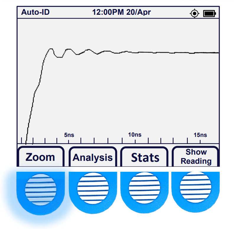
A Waveform can be generated on the ‘Sensor Reading’ screen. Press the ‘Show Waveform’ button. After a few moments, a graph will be generated showing the steps in the reflected EM signal in a high-resolution waveform. For a closer look at the waveform, press ‘Zoom’. After pressing Show Waveform, the waveform data is logged in the Reader’s memory and can be retrieved via .csv export later. You can return to the data by pressing ‘Show Reading’.
Sensor Readings
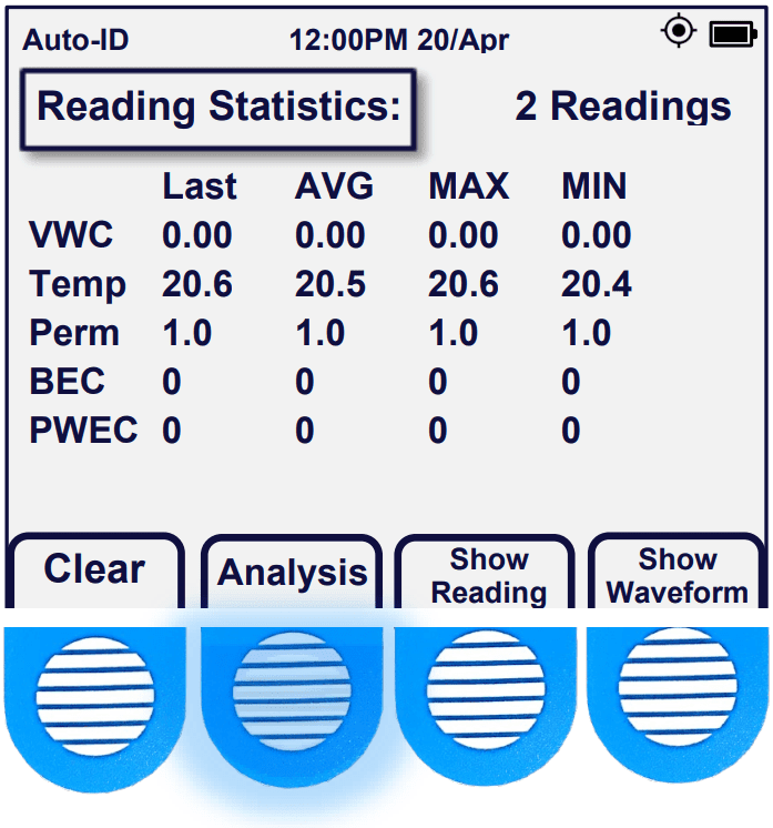
From the Sensor Reading page, you will also have the ‘Stats’ and ‘Analysis’ options. Pressing the ‘Stats’ button will display the number of readings from which the averages, maximums, and minimums are taken. To disregard previous readings and begin a new set you will need to press the ‘Clear‘ button on the ‘Reading Statistics’ page.
Note: At this stage, if you have multiple sensors connected, you can collect
readings from the other sensors by pressing ‘Select Sensor’. You can then move to the next sensor by pressing ‘Next Sensor’, then take a new Reading by pressing ‘Read Sensor’.
If you press the ‘Analysis‘ button, you will be presented with the ‘Reading Analysis’ screen which can be useful for indicating the fill level of the soil’s field capacity (FC). The analysis will not provide accurate data unless thresholds are preconfigured by the user.
Note: While on any of the four options: ‘Sensor Reading’, ‘Waveform’, ‘Reading Statistics’, or ‘Reading Analysis’ screens, pressing the ‘Read Sensor‘ button will refresh that screen with the newest data being collected and log a new reading.
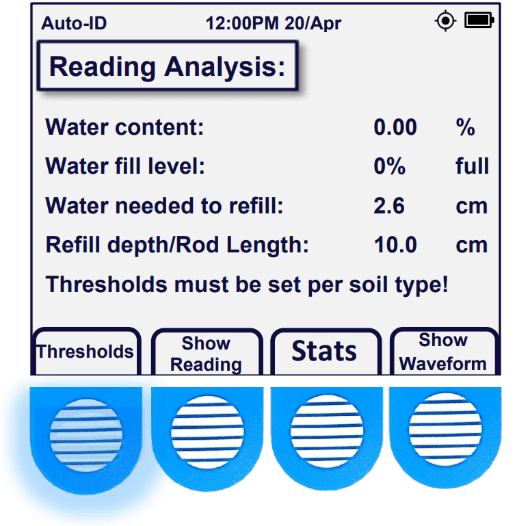
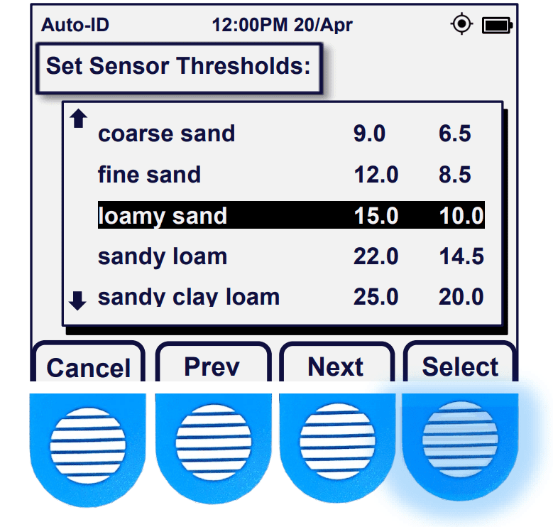
Press ‘Thresholds’ to adjust sensor thresholds per soil type.
Thresholds
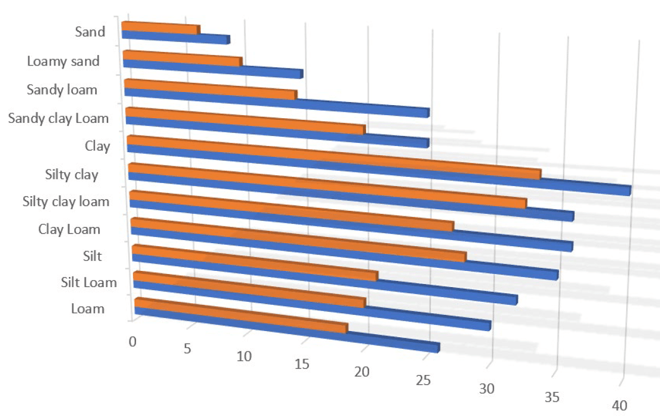
Soil-Types/Water Thresholds
To modify sensor thresholds, first take a sensor reading by pressing the ‘Read Sensor’ button, then press ‘Analysis’ then press the ‘Thresholds’ button. Once on the ‘Set Sensor Thresholds’ page, you can modify the Soil Type, the Field Capacity, and the Managed Allowable Depletion. Change the Soil Type by pressing ‘Change ST’.

After pressing ‘Change ST’, you can change the soil type by cycling through the predetermined options in the windowed listing. Use the ‘Next’ and ‘Prev’ buttons to move up or down through the list. Press ‘Select’ when you have found the soil type that most closely matches the soil that the sensor is being inserted into.
Once a soil type has been selected, its Field Capacity and Managed Allowable Depletion can be modified using the [+1, -1 and +0.1] buttons. When the value has been modified, press ‘Done’ to confirm the changes.
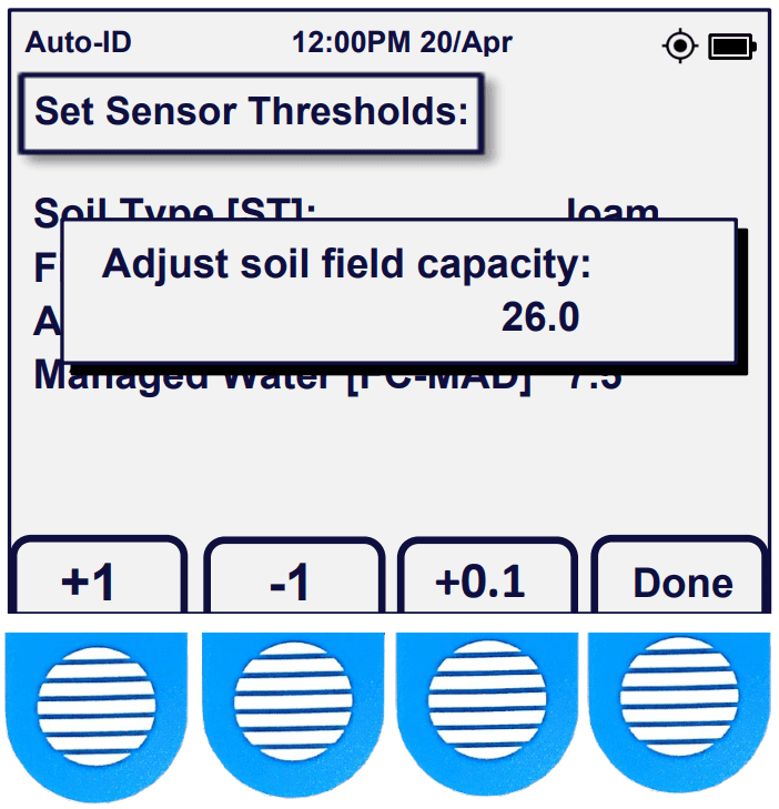
Note: Only change the defaulted values after careful consideration has been taken regarding the impacts of the changes.
Field Capacity
Understanding Field Capacity
This wetness scale gives a depiction of the important stages of soil water content starting with Saturation at the top, where soil water content exceeds the surface tension of the soil particles driving the water down into the subsoil, washing away critical nutrients with it and potentially rotting the roots.
Field Capacity is the ideal soil water content that allows moisture, nutrients, and oxygen to stay around the roots.

The Managed Allowable Depletion level is the lowest that soil moisture can go without permanently harming or killing the plant. The customized ‘Allowed depletion limit’ can be set to a chosen value using the navigation buttons if desired.
Each soil type has its own unique characteristics. Acclima has characterized many soil types and has provided default values within the Reader’s operating system that can be used as a guide for irrigation. However, each site will have its unique properties, so it is important to monitor the irrigation levels to best suit the health of the crops being nurtured. Increase or decrease the values found on the thresholds page to better suit the crops’ needs.
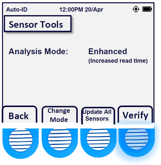
Enhanced Analysis Mode
Using the Enhanced analysis mode
Some sensors may utilize an enhanced statistical analysis mode when collecting readings. This Mode may improve readings, by causing the sensor to perform improved statistical processing to better stabilize readings at the cost of power consumption and speed.
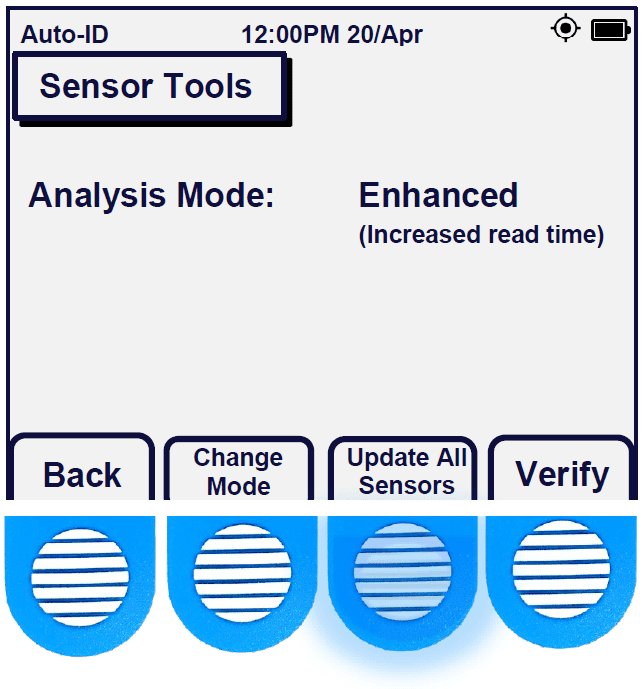
To enable Enhanced Analysis mode, press the button for ‘Sensor’ on the home page. Then select the “Tools”.
If the detected sensor is compatible with the Enhanced Mode feature, a “Change Mode” button will be present.
On the ‘Sensor Tools’ page, press “Change Mode” to change the analysis mode from ‘Normal’ to “Enhanced”.
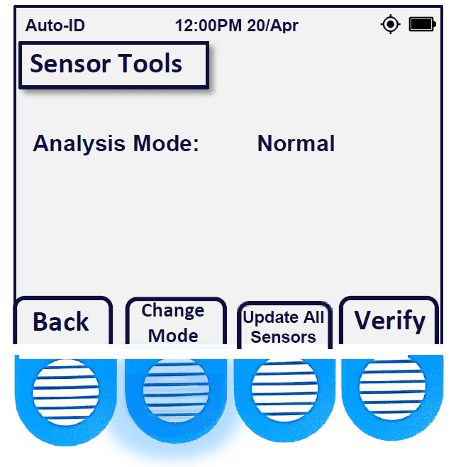 Note: The “Change Mode” option is not available in all sensor models or firmware versions.
Once in the Enhanced Mode, the sensor will remain there until it is changed back to normal mode. Noisy readings will be smoothed due to the number of samples scanned will have been greatly increased.
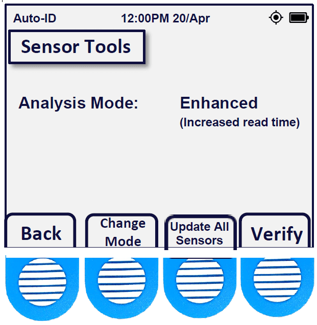
Note: The “Enhanced Mode” feature is compatible with “Bussed Mode”.
Verify Command
Per Sensor Diagnostic Tool
Sensors displaying odd characteristics can be further troubleshooted with a nifty tool built into the Acclima Reader. This tool runs the V (verify command) found in the SDI-12 protocol.
To perform the ‘Verify’ command. Press the button for ‘Sensor’ on the home page, then press ‘Tools’.
Press the “Verify” button, to run the brief sensor diagnostic.
After the verify command is performed, five vital data points will be observed.
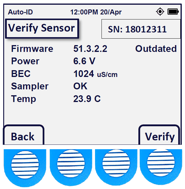
The firmware version is verified against an internal database containing all recent Acclima sensor firmware versions. Power to the sensor is tested to check the cable run for potential issues with the cable. Bulk EC is tested to retrieve any result within operating specification for that sensor model. The sensor’s digitizer is tested to verify samples(readings) are possible. Temperature is also tested to verify the sensor’s thermistor.
Warnings may appear next to these readings and actions should be taken to correct the issues when they arise.
Bussed Mode
Multiple Sensors
By default, only one sensor can be viewed at a time. Enabling “Bussed Mode” allows up to 62 SDI-12 unique devices to be detected at once.
To enable Bussed Mode, simply reach page 2/3 from the ‘Sensor Setup’ by pressing the “-More-” button.
The Address Mode will be set to ‘One Sensor’ by default. Press the “Address Mode” option to change it to ‘Bussed Mode’.
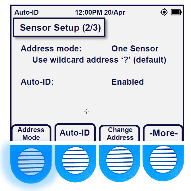
After entering ‘Bussed Mode’, a Bus icon appears in the top left header of the Reader display.
After entering ‘Bussed Mode’ it is recommended to press the ‘Scan’ button to populate the detected sensors.
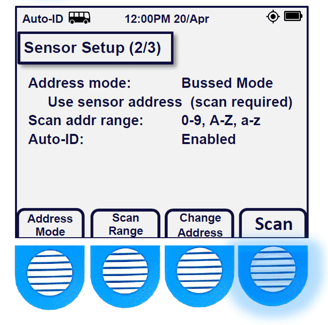
Note: Each sensor attached must have a unique address or they will not populate and otherwise be invisible in bussed mode.
Sensor Addressing
How to Address SDI-12 Devices
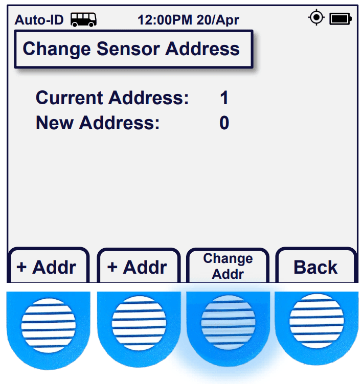
In ‘Bussed Mode’ each sensor connected to the Reader should have a unique sensor address. The sensor’s address allows the reader to differentiate each of the sensors from one another. Each sensor can choose a single identifying character as its ‘address’, which can be any of these types of characters: [0-9], [A-Z] or [a-z]. By default, the address will be set to “0”.
With a single sensor connected in the ‘Sensor Setup’ page press ‘Change Address’.
With a single sensor connected from the home page, press ‘Sensor’, then press ‘Detect’. This action will prompt the sensor to reply with its identifying information or an error. To change the address, press ‘-More-‘ and then press ‘Change Address’.
The current address will be displayed, and the new address can be cycled through from 0-9, A-Z or a- z by pressing the [+ Addr] or [- Addr] buttons.
Once the address is chosen, confirm it by pressing ‘Change Addr’.
Press “Home” button, then “Sensor” to see the new address on the “Sensor Setup” 1/3 page.
Note: If two or more sensors use the same address, they will not be detected by the Reader, even in Bussed Mode.
Firmware Updates
Updating Sensor Firmware
Sensor firmware updates can be sent to single or bussed sensors anytime a new update has become available.
First, load the update file onto the Acclima USB drive using the folder structure: Acclima\RD1200\Updates.
Insert the USB drive into the micro-USB port on the Reader. The Reader will synchronize and copy the files into the Reader’s memory.
Press the ‘Home’ button, then the ‘Sensor’ option.
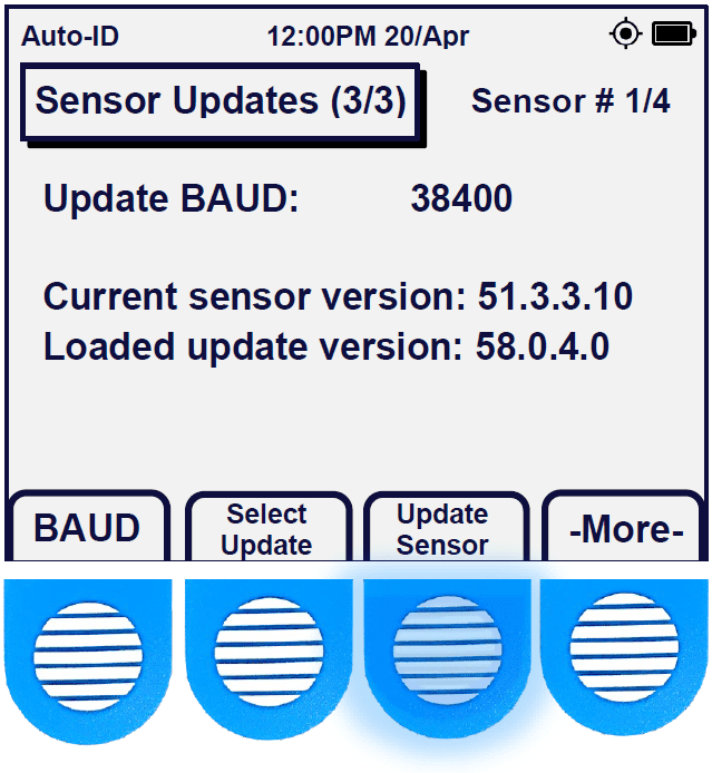
On the ‘Sensor Setup page 1/3’. Press the ‘-More-‘ button until you reach ‘Sensor Setup page 3/3’. Then press, “Select Update”.
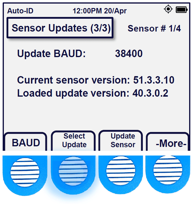
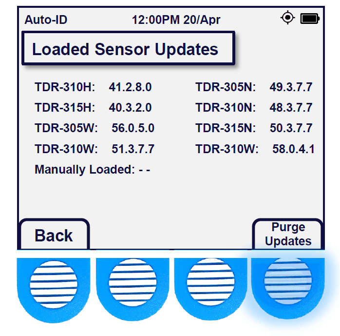
Here, sensor firmware can be viewed on the page by pressing the “Show Updates” button. The Reader’s memory can be cleared of these updates by pressing “Purge Updates”.
On Sensor Updates (3/3), Press ‘Update Sensor’ to perform a sensor update.
A progress bar will appear, including the selected sensor’s serial number. When the progress is complete, you will see “Confirming” and “Success” after the update has been verified.
Note: If the update speed is too fast or slow, it can be modified by adjusting the BAUD rate.
Update All Sensors at Once
Multiple sensors can be updated at once using the Update All Sensors function.
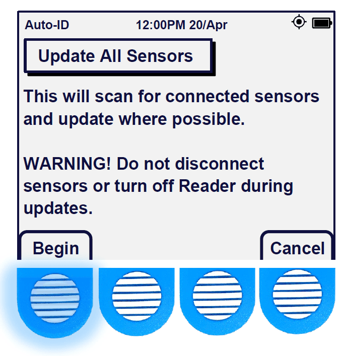
To update one or more sensors automatically, press the ‘Sensors’ button on the home page. After reaching ‘Sensor Setup page 1/3’ press the “Tools” button.
On the Sensor Tools page press “Update All Sensors”, on the following page a description of the events and a warning to not disconnect the sensor’s or turn off the power to the Reader, while the update is in progress becomes visible.
Press “Begin” to start the update procedure.
The Reader will perform the following tasks in sequence and can be canceled at any time.
- Enter the Reader into Bussed mode.
- Perform a scan using the aMI command to detect connected sensors.
- The Reader will then send packet data to the sensors to determine the most suitable BAUD rate.
- The Reader will then deliver the update file found on the Reader to the sensor.
- The Reader will auto-adjust the BAUD rate to 2400, if an update fails to load.
- When completed, a report is made available that details the number of sensors updated, and those that were not.
- The report will time out in accordance with the Sleep settings
BAUD Rate
Changing Update Speeds
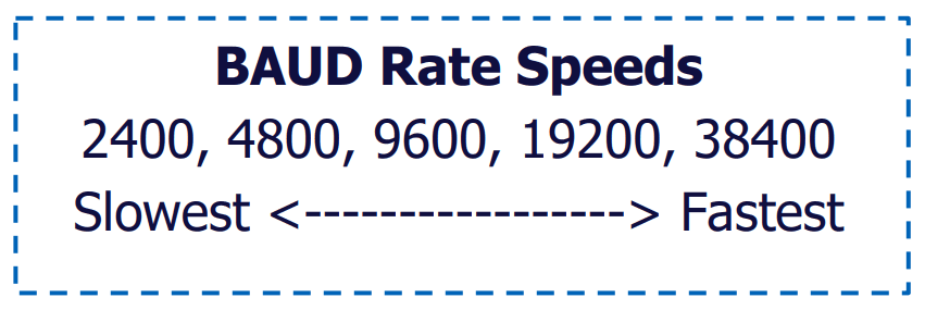
When a sensor update fails it can be because of several reasons. The most common is that there may be too many sensors attached or the cables may be too long making it difficult for larger data files to be transmitted to the sensor without error. Adjusting the BAUD rate may improve the ability to transmit the updated file so that the sensor can receive it accordingly.
To change the BAUD rate, Press the ‘Sensor’ button on the homepage, and navigate to the ‘Sensor Updates’ page (3/3) by pressing the ‘-More-‘ button twice.
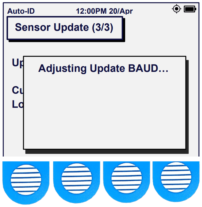
Here, you may press the “BAUD” button.
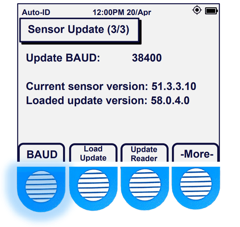
The default BAUD rate is set to 38400, which is the fastest setting available. However, multi-sensor configs, long cable runs and low power draw sensors may not complete updates at the fastest transfer speeds. Pressing the “BAUD” button reduces the BAUD rate until it resets back to the default speed of 38400.
Note: Only drop to the lowest BAUD rate when all other BAUD rates have proven unsuccessful at updating the sensor firmware.
Data Exporting
Data Options
From the ‘Home Screen’ press the ‘Data’ button. The ‘Data’ page provides you with the memory usage information (must be at least 1% to show up). You can select your preferred ‘Data Output‘ by pressing that button and toggling through ‘CSV” only, ‘CSV and binary’, or just ‘binary’. This data will then be able to be transferred to your micro-USB drive in the preferred format when it is plugged into the Reader.
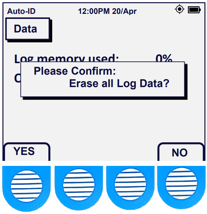
The ‘Erase Logs‘ button allows you to erase all log data.
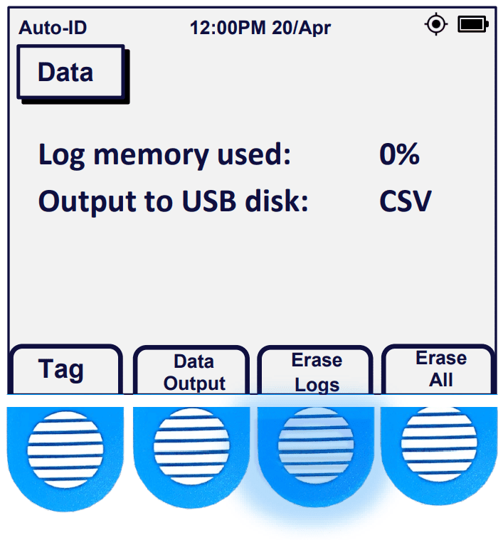
But the screen requires you to confirm by pressing a ‘YES‘ or ‘NO‘ button. Similarly, the ‘Erase All‘ enables you to erase all log and configuration data, also with a confirmation of ‘YES‘ or ‘NO‘.
On the ‘Data’ screen you can access the Data Tag feature screen by pressing ‘Tag‘. The ‘Data Tag’ screen gives you control to group your readings with a specified identification number.
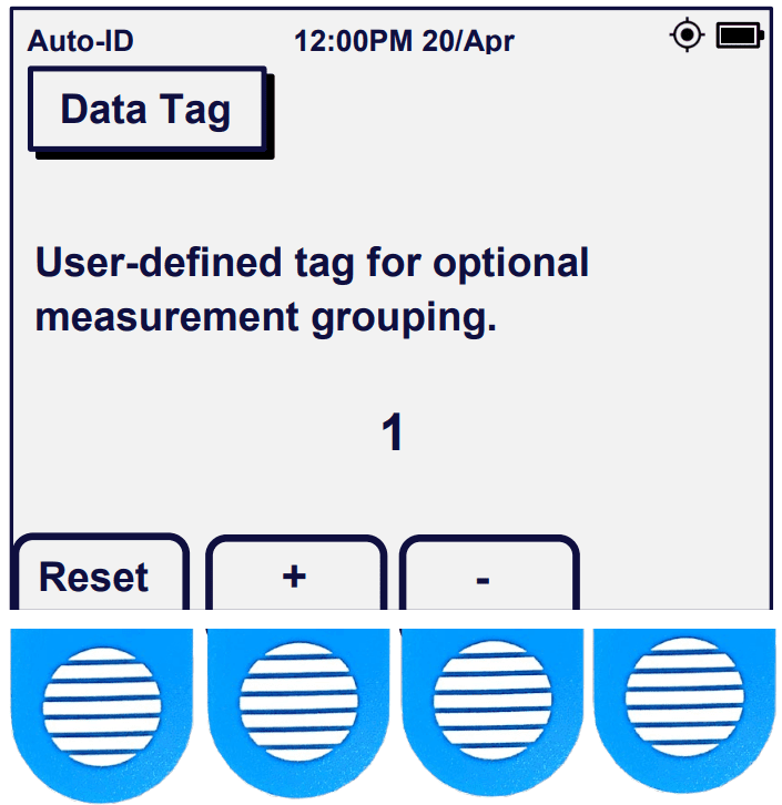
Once a number has been selected all subsequent readings will be associated with that number which will be visible in your exported data.
Acclima USB Sync
1st Retrieving Reading Log Data
To export your data for viewing on a computer, insert the micro-USB connector on the 64-gigabyte Acclima thumb drive into the micro-USB port on the side of the Acclima Reader. All the Reader’s records, including readings and captured waveforms, will be synchronized onto the USB drive, which can then be connected to your computer’s USB-A port for downloading to the PC and viewing in a .CSV file. This file will be saved in the Acclima\RD1200\Updates\Data folder. We recommend using Microsoft Excel™ to view the file data.

Caution: Do not disconnect the thumb drive until the Reader indicates the synchronization is complete. Please note that data can only be transferred using a thumb drive. A direct connection with a cable between the PC and the Reader will only charge the Reader’s battery, and not transfer data. If there are Reader firmware or sensor updates remaining after the logs have synchronized, reinsert the USB again to complete each remaining synchronization.
2nd Upgrading the Reader’s Firmware
If you desire to apply a new firmware update onto the Reader from the Acclima.com website. You should first download it into the Acclima\RD1200\Updates folder, on the micro-USB flash drive. Plugging in a new flash drive into the Reader will automatically create this folder structure inside your drive. Then when you plug the flash drive into the micro-USB port on the Sensor Reader (while powered on), it will automatically update the Reader’s firmware. Caution: Let this process complete, uninterrupted by waiting until you see the message ‘Synchronization Complete’ before removing the thumb drive. The Reader will only update if it finds a firmware file version in the USB directory that is newer than the one it has in its memory.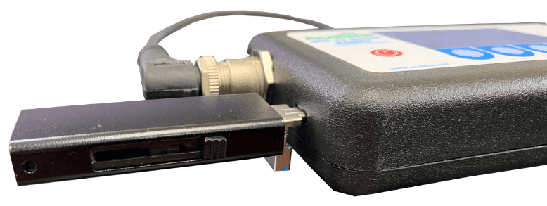
3rd Upgrading the Reader’s Firmware
After the Logs and Reader firmware have been synchronized you can then sync sensor firmware by plugging in the micro-USB drive into the Reader’s port. Additionally, you can also load multiple sensors updates into the same folder. The Reader will Load the newest updates from the USB onto its’ memory, so that when that sensor model is detected its firmware can be updated. The Reader supports nine updates at once, and one more if the USB is kept plugged in while performing sensor updates.